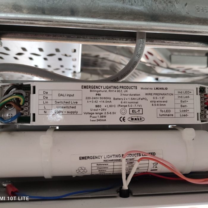
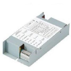
ELP LM240LID KIT For Sale
- Estimated Delivery : Up to 4 business days
- Free Shipping & Returns : On all orders over $200
LDM – LED Array Emergency Control Gear
LDM Range
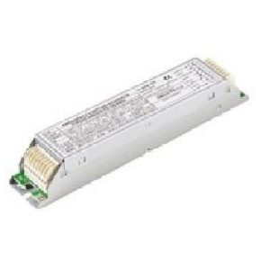
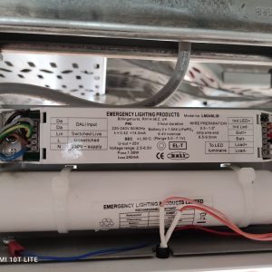
The ELP ENEC marked LDM emergency LED control gear allows emergency lighting operation of high-power LED modules when used in conjunction with the standard mains voltage LED control gear.
The emergency control gear incorporates a module charger and a high temperature Nickel Cadmium or Lithium Iron Phosphate (LiFePO4) battery. In the event of a mains failure an integral 2-pole relay disconnects the LED lighting load from the mains control gear and then connects it to the emergency control gear which operates the LED module at an optimum light output for the rated duration.
- The LED current in emergency mode is automatically adjusted for maximum light output and is constant for the entire rated duration.
-
- Smart charging of both Nickel Cadmium and Lithium Iron Phosphate batteries. NB: Lithium Iron Phosphate batteries offer long life (up to 10 years).
-
- Details are logged of any mains failures to assist in the diagnostics of any site issues.
-
- The LDM range is available with fully interoperable DALI control and reporting function. These DALI versions indicated by the suffix D, also provide automatic Self-Test when no DALI bus is connected.
-
It is important to note that some LED mains control gear should not be operated with an open circuit load, to overcome this problem the LDM range features a live in live out relay which ensures the load is in place before the mains driver is powered up.
In Self-test mode the function and duration tests will take place at randomised times. If required, testing can be programmed to occur at a designated time by turning the unswitched supply off and on 3 times in 10 seconds at the required time. Note: The function test will occur weekly at the same time.
SECTION
SUBJECT
PLASTIC HOUSED MODULE
Environmental
Protection against electric shock
Secondary outputs – SELV for output voltage < 100V
Ingress protection
IP20
Module rated operating ambient temperature
-20°C to 50°C
Battery rated operating ambient temperature
0°C to 55°C
Maximum case temperature
65°C
Mains Operation
Rated voltage supply
220 240V AC
Mains frequency
50 60Hz
Mains supply current
<18mA
Mains supply power
4 watts
Power factor
0.53C
Mains overvoltage protection
320 volts for 1 hour
Indicator LED
2 wire green colour – standard LDM
2 wire red green – DALI LDM
Maximum power that can be switched via relay contacts
150 watts
Maximum current that can be switched via relay contacts
3 amps
Maximum voltage that can be switched via relay contacts
250V AC 220V DC
Emergency Operation
Emergency duration
1 or 3 hours
Battery chemistry type
NiCd or LiFePO4
Number and type of high temperature cells
LDM90 and LDM90D
4 x NiCd 1.8Ah sub-C cells
LDM200 and LDM200D
5 x NiCd 1.8Ah sub-C cells
LDM90MO, LDM200MO, LDM90MOD and LDM200MOD
2 x LiFePO4 2.1Ah 22650 cells
LDM90HO, LDM200HO, LDM90HOD and LDM200HOD
2 x LiFePO4 3Ah 26650 cells
Battery recharge period
<24 hours
Time to full illuminance
<0.5 seconds
Short-circuit-proof battery connection, polarity reversal and deep discharge protection
Battery charge current
NiCd 1.8Ah sub-C cells 2 stage charge – boost trickle
LiFePO4 2.1Ah and 3Ah cells – voltage dependent, constant current
100mA 70mA ±10%
0 – 150mA
Battery discharge current range (at nominal battery voltage)
NiCd 1.8Ah sub-C cells
LiFePO4 2.1Ah 26650 cells
LiFePO4 3Ah 26650 cells
360mA to 560mA (450mA)
475mA to 735mA (550mA)
650mA to 1000mA (750mA)
Module operating current – see separate graphs.
LDM90 and LDM90D
134mA to 19mA ±10%
LDM90MO and LDM90MOD
200mA to 30mA ±10%
LDM90HO and LDM90HOD
258mA to 41mA ±10%
LDM200 and LDM200D
33mA to 10mA ±10%
LDM200MO and LDM200MOD
40mA to 12mA ±10%
LDM200HO and LDM200HOD
57mA to 18mA ±10%
Module output voltage range (nominal power)
LDM90 and LDM90D
12V to 90V (1.6W)
LDM90MO and LDM90MOD
12V to 90V (2.6W)
LDM90HO and LDM90HOD
12V to 90V (3.5W)
LDM200 and LDM200D
60V to 200V (2.0W)
LDM200MO and LDM200MOD
60V to 200V (2.4W)
LDM200HO and LDM200HOD
60V to 200V (3.5W)
EOFI – dependant on LED module type
0.12 to 0.25
A record is kept of the number and length of emergency and mains operations – this information can be downloaded via the internal programming connector
Mechanical
Module outside dimensions
178mm (L) x 30mm (W) x 21mm (H)
Fixing centres
174mm
Electrical connections
Push wire terminals
Standards Compliance
EN61347-1, EN61347-2-7, EN61347-2-13 and EN62384
Yes
EN62034*, EN62386-101*, EN62386-102* and EN62386-202*
Yes
EN55015
Yes
EN61547
Yes
Marks CE
Yes
Title
Default Title
Review Cart
LDM Range
The ELP ENEC marked LDM emergency LED control gear allows emergency lighting operation of high-power LED modules when used in conjunction with the standard mains voltage LED control gear.
The emergency control gear incorporates a module charger and a high temperature Nickel Cadmium or Lithium Iron Phosphate (LiFePO4) battery. In the event of a mains failure an integral 2-pole relay disconnects the LED lighting load from the mains control gear and then connects it to the emergency control gear which operates the LED module at an optimum light output for the rated duration.
- The LED current in emergency mode is automatically adjusted for maximum light output and is constant for the entire rated duration.
- Smart charging of both Nickel Cadmium and Lithium Iron Phosphate batteries. NB: Lithium Iron Phosphate batteries offer long life (up to 10 years).
- Details are logged of any mains failures to assist in the diagnostics of any site issues.
- The LDM range is available with fully interoperable DALI control and reporting function. These DALI versions indicated by the suffix D, also provide automatic Self-Test when no DALI bus is connected.
It is important to note that some LED mains control gear should not be operated with an open circuit load, to overcome this problem the LDM range features a live in live out relay which ensures the load is in place before the mains driver is powered up.
In Self-test mode the function and duration tests will take place at randomised times. If required, testing can be programmed to occur at a designated time by turning the unswitched supply off and on 3 times in 10 seconds at the required time. Note: The function test will occur weekly at the same time.
SECTION SUBJECT PLASTIC HOUSED MODULE Environmental Protection against electric shock Secondary outputs – SELV for output voltage < 100V Ingress protection IP20 Module rated operating ambient temperature -20°C to 50°C Battery rated operating ambient temperature 0°C to 55°C Maximum case temperature 65°C Mains Operation Rated voltage supply 220 240V AC Mains frequency 50 60Hz Mains supply current <18mA Mains supply power 4 watts Power factor 0.53C Mains overvoltage protection 320 volts for 1 hour Indicator LED 2 wire green colour – standard LDM
2 wire red green – DALI LDMMaximum power that can be switched via relay contacts 150 watts Maximum current that can be switched via relay contacts 3 amps Maximum voltage that can be switched via relay contacts 250V AC 220V DC Emergency Operation Emergency duration 1 or 3 hours Battery chemistry type NiCd or LiFePO4 Number and type of high temperature cells
LDM90 and LDM90D
4 x NiCd 1.8Ah sub-C cellsLDM200 and LDM200D 5 x NiCd 1.8Ah sub-C cells LDM90MO, LDM200MO, LDM90MOD and LDM200MOD 2 x LiFePO4 2.1Ah 22650 cells LDM90HO, LDM200HO, LDM90HOD and LDM200HOD 2 x LiFePO4 3Ah 26650 cells Battery recharge period <24 hours Time to full illuminance <0.5 seconds Short-circuit-proof battery connection, polarity reversal and deep discharge protection Battery charge current
NiCd 1.8Ah sub-C cells 2 stage charge – boost trickle
LiFePO4 2.1Ah and 3Ah cells – voltage dependent, constant current
100mA 70mA ±10%
0 – 150mABattery discharge current range (at nominal battery voltage)
NiCd 1.8Ah sub-C cells
LiFePO4 2.1Ah 26650 cells
LiFePO4 3Ah 26650 cells
360mA to 560mA (450mA)
475mA to 735mA (550mA)
650mA to 1000mA (750mA)Module operating current – see separate graphs.
LDM90 and LDM90D
134mA to 19mA ±10%LDM90MO and LDM90MOD 200mA to 30mA ±10% LDM90HO and LDM90HOD 258mA to 41mA ±10% LDM200 and LDM200D 33mA to 10mA ±10% LDM200MO and LDM200MOD 40mA to 12mA ±10% LDM200HO and LDM200HOD 57mA to 18mA ±10% Module output voltage range (nominal power)
LDM90 and LDM90D
12V to 90V (1.6W)LDM90MO and LDM90MOD 12V to 90V (2.6W) LDM90HO and LDM90HOD 12V to 90V (3.5W) LDM200 and LDM200D 60V to 200V (2.0W) LDM200MO and LDM200MOD 60V to 200V (2.4W) LDM200HO and LDM200HOD 60V to 200V (3.5W) EOFI – dependant on LED module type 0.12 to 0.25 A record is kept of the number and length of emergency and mains operations – this information can be downloaded via the internal programming connector Mechanical Module outside dimensions 178mm (L) x 30mm (W) x 21mm (H) Fixing centres 174mm Electrical connections Push wire terminals Standards Compliance EN61347-1, EN61347-2-7, EN61347-2-13 and EN62384 Yes EN62034*, EN62386-101*, EN62386-102* and EN62386-202* Yes EN55015 Yes EN61547 Yes Marks CE Yes Title Default Title
Review Cart
